Comprehensive Guide to Six Major Hardness Testers
In industrial production, quality testing, and scientific research, hardness is a key property for understanding metals and other materials. The most common tool for measuring hardness is the hardness tester. There are many types, such as Brinell, Rockwell, Vickers, Leeb, Webster, and Ultrasonic hardness testers. Each type has different testing principles and applications. Some are better for large castings, others for precision parts, and some are ideal for quick on-site testing. This article will explain the principles, applications, and pros and cons of these six common hardness testers.
I. Brinell Hardness Tester
1. Principle
A carbide ball with a diameter D is pressed into the surface of the sample with a test force F. The force is held for 10–15 seconds, then released. A round indentation forms on the surface. The Brinell hardness value is the average pressure applied over the area of this spherical indentation.
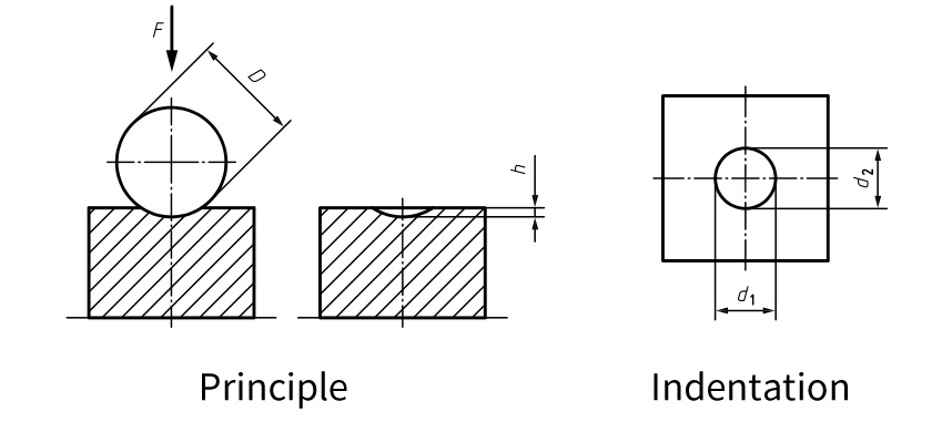
2. Calculation Method

The following is an example of the designation of Brinell hardness, HBW.
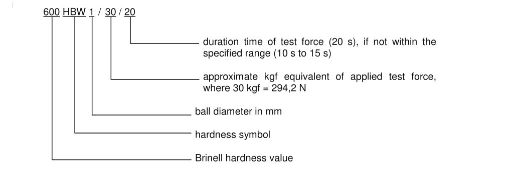
3. Selection of Ball Diameter and Load Ratio
Standard ball diameters: 10 mm, 5 mm, 2.5 mm, 1 mm
“0.102F/D²” ratio options: 30, 15, 10, 5, 2.5, 1
Common ratio selection
0.102F/D² = 30: General carbon steel, 45# steel, quenched and tempered steel, gray cast iron, ductile cast iron, aluminum alloys. This is the standard ratio, suitable for most metals and mechanical parts.
0.102F/D² = 15: Medium- and low-hardness steel, annealed steel, brass, bronze, low-hardness aluminum alloys. Suitable for medium-hardness materials or thinner parts. Leaves moderate indentations and avoids structural damage.
0.102F/D² = 10: Pure aluminum, soft copper, soft brass, low-strength aluminum alloys, annealed non-ferrous metals. Ideal for soft metals, thin parts, or sensitive surfaces, with shallow indentations.
0.102F/D² = 5: Soft lead, soft tin, some low-density alloys, polymers. For very soft materials or surface testing, prevents deep indentations.
0.102F/D² = 2.5: Ultra-soft lead, ultra-soft tin, light metals, flexible polymers. Used for extremely soft or research materials.
0.102F/D² = 1: Ultra-pure lead, ultra-soft tin, rubber, special low-hardness composites. Mainly for experiments or special material analysis.
The ball diameter depends on the sample thickness and size. In industry, the 10 mm ball is most common. For smaller or thinner samples, smaller balls can be used, but the load must also be reduced to keep the F/D² ratio constant.
4. Suitable Testing Materials
The Brinell hardness tester is used for larger metal samples with medium to low hardness (usually between 8–650 HBW). Because of its large ball indenter, high test force, and wide indentation, it is ideal for metals with coarse grains, softer textures, or uneven structures. Typical examples include annealed medium- and low-carbon steel, cast iron, cast steel, and non-ferrous metals such as aluminum, copper, bronze, and their alloys.
The sample thickness should be at least 8 times the average depth of the indentation to ensure no deformation appears on the back after testing.
The surface roughness should be no greater than 1.6 μm to avoid affecting the accuracy of the indentation diameter measurement.
5. Advantages and Disadvantages
Advantages:
Large indentation reflects the average hardness over a wide area, giving reliable and repeatable results.
Can measure coarse-grained or uneven materials, ideal for castings and forgings.
Less affected by fine structure; surface roughness requirement is relatively lower than that of a Vickers hardness tester.
For steel and cast iron, hardness roughly correlates with tensile strength, making conversion easy.
Disadvantages:
Large force takes time, so testing efficiency is low.
Indentation is obvious, making it a destructive test that damages the workpiece surface.
High force can penetrate thin plates or deform small parts, unsuitable for thin or small samples.
Not suitable for very hard materials; high forces may deform the indenter.
Different metals (e.g., soft metals vs. steel) need different test conditions, so results are not directly comparable.
II. Rockwell Hardness Tester
1. Principle
A specific indenter, with a set size, shape, and material, is pressed against the sample surface with an initial test force F₀, and the initial indentation depth(h₀) is measured. Then the main test force F₁ is applied. After removing F₁ and keeping F₀, the final indentation depth(h₁) is measured. The Rockwell hardness is determined by the depth increase (h₁ − h₀) of the indentation.
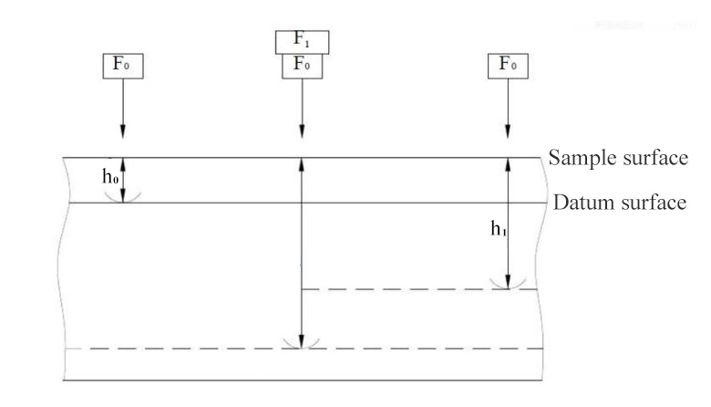
2. Calculation Method

3. Rockwell Hardness Indenter Types and Test Force Selection
Rockwell hardness testing mainly uses two types of indenters: a diamond cone indenter and a tungsten carbide ball indenter.
Diamond Cone Indenter: Used for testing high-hardness materials, such as quenched steel and hard alloys. Common scales include HRA, HRC, and HRD.
Tungsten Carbide Ball Indenter: Used for testing softer materials, such as annealed steel and non-ferrous metals. The most common is a 1/16-inch ball, suitable for HRB, HRF, and HRG scales.
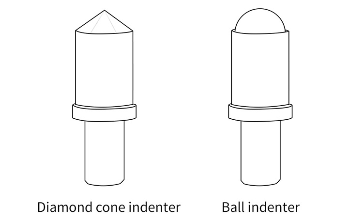
Rockwell testing applies force in two steps:
Preliminary Test Force: Fixed at 10 kgf. It sets the zero reference point.
Main Test Force: Varies depending on the selected scale.
Total Test Force = Preliminary Test Force + Main Test Force.
Common Rockwell Scales: Indenter and Test Force
HRA: 120° diamond cone, total force 60 kgf. Small force and shallow indentation, used for hard and thin materials.
HRB: 1/16 inch steel ball, total force 100 kgf. Most common for soft steel and non-ferrous metals.
HRC: 120° diamond cone, total force 150 kgf. Most common for hardened steel.
4. Suitable Testing Materials
The Rockwell hardness tester is widely used. Different scales (combinations of indenter and test force) cover a wide range of materials, from very soft to very hard. This includes hardened steel, non-ferrous metals, thin plates, and surface-hardened layers.
Common scales:
HRA: Rockwell hardness range 22-88 HRA. Suitable for very hard materials like hard alloys and quenched tool steel, and for thin hard materials such as thin steel sheets and coatings. Commonly used to test hard alloy tools (e.g., lathe tool bits), car engine valves, and metal coatings like galvanized or chrome-plated layers. The small indentation helps avoid damaging the coating.
HRB: Rockwell hardness range 20-100 HRB. Suitable for soft metals such as annealed steel, copper alloys, aluminum alloys, and soft steel. Often used for testing aluminum profiles (e.g., window and door frames), aluminum alloy sheets, copper parts (e.g., wire terminals, copper pipes), and low-carbon steel after annealing (e.g., standard steel plates, iron nails).
HRC: Rockwell hardness range 20-70 HRC. Suitable for medium to high hardness metals, such as quenched steel, tempered steel, and high-hardness cast iron. Commonly used to test core components of machinery (e.g., gears, bearings, shafts), cutting tools, stamping dies, and injection molds.
Surface Rockwell (N, T) scales are suitable for thin parts, surface-treated layers, and small components.
For tests using a diamond cone indenter, the thickness of the specimen or the test layer should be no less than 10 times the residual indentation depth. For tests using a ball indenter, the thickness of the specimen or the test layer should be no less than 15 times the residual indentation depth.
The surface roughness of the specimen should not exceed 0.8 μm; for industrial applications with lower accuracy requirements or for softer materials, this requirement can be relaxed to 1.6 μm.
5. Advantages and Disadvantages
Advantages:
Easy and fast to operate; hardness can be read directly from the dial or digital display, making it ideal for quick on-site checks.
Smaller indentation than Brinell, so the workpiece can still be used.
Multiple scales cover a wide range, from soft to hard materials.
Initial test force can penetrate light surface oxidation or rough spots, so surface smoothness requirements are low.
Disadvantages:
Small indentation reflects only local hardness; repeatability and accuracy are lower for uneven materials. Multiple measurements are needed for an average.
Deep indentation may penetrate thin layers and measure the substrate, so it is unsuitable for very thin or shallow surface layers.
Different scales use different forces and indenters; results cannot be directly compared.
III. Vickers Hardness Tester
1. Principle
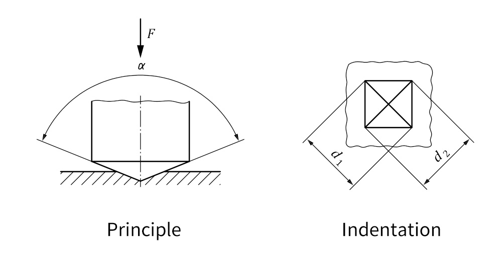
A square-based diamond pyramid indenter (usually with a 136° angle) is pressed into the sample surface with a test force F. After holding for a short time, the force is removed. The lengths of the two diagonals (d) of the indentation are measured. The Vickers hardness value is the ratio of the test force to the indentation surface area.
2. Calculation Method

3. Suitable Testing Materials
The Vickers hardness tester is highly versatile. It can measure almost all uniform solid materials, from very soft (lead, aluminum, copper) to very hard (hardened high-carbon steel, cemented carbide). It is especially suitable for surface-hardened layers, plated coatings, and small, thin, or precision parts. It can also measure microhardness of specific microstructures under a metallurgical microscope, such as the hardness of ferrite or carbides in steel.
The specimen or test layer thickness should be at least 1.5 times the indentation diagonal. After testing, no visible deformation should appear on the back of the specimen.
The surface roughness should not exceed 0.2μm, ideally not exceed 0.1μm, achieving a mirror or near-mirror finish.
4. Advantages and Disadvantages
Advantages:
The indentation shape remains similar under any test force. This means Vickers hardness values at different forces are consistent and comparable.
Very wide testing range; one device can measure materials from very soft (ceramics, coatings) to very hard (carbides) without changing the indenter or scale.
High resolution and precision, ideal for research and precise quality control.
Excellent for thin, small, surface-treated layers, and microscopic structures.
Micro Vickers testers can measure the hardness of specific microstructures, such as single grains.
Causes minimal damage to materials, making it nearly non-destructive.
Disadvantages:
Requires a very smooth surface, close to mirror finish; scratches or roughness can affect diagonal measurements.
Not suitable for uneven or coarse-grained materials that irregular indentations make accurate measurement difficult and reduce repeatability.
Traditional manual testers require microscope observation and manual measurement, which is slow and prone to human error.
A complete Vickers tester integrates precision loading and high-resolution optics, making it much more expensive than other hardness testers.
IV. Leeb Hardness Tester
1. Principle
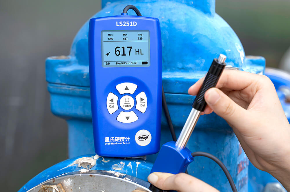
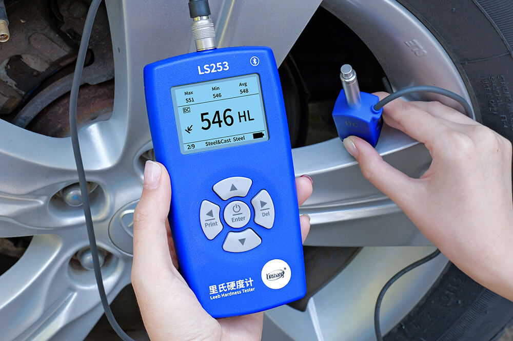
Leeb hardness is a dynamic testing method. A small impact body with a fixed mass strikes the sample surface vertically at a set speed. The hardness value is calculated from the ratio of the rebound speed (VR) to the impact speed (VA) measured about 1 mm above the surface.
Leeb hardness tester measurement principle
2. Calculation Method

3. Sample Mass and Thickness Requirements
Select the impact device and tester type based on the sample’s mass and thickness. If the sample mass is below the allowed minimum, or if the mass is enough but the local thickness is below the required limit, the test results may be affected. In such cases, the sample should be rigidly supported or firmly coupled to a solid base during testing.

4. Applications of Impact Devices
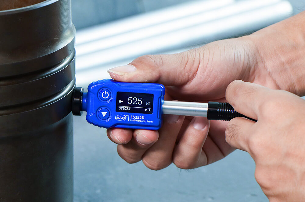
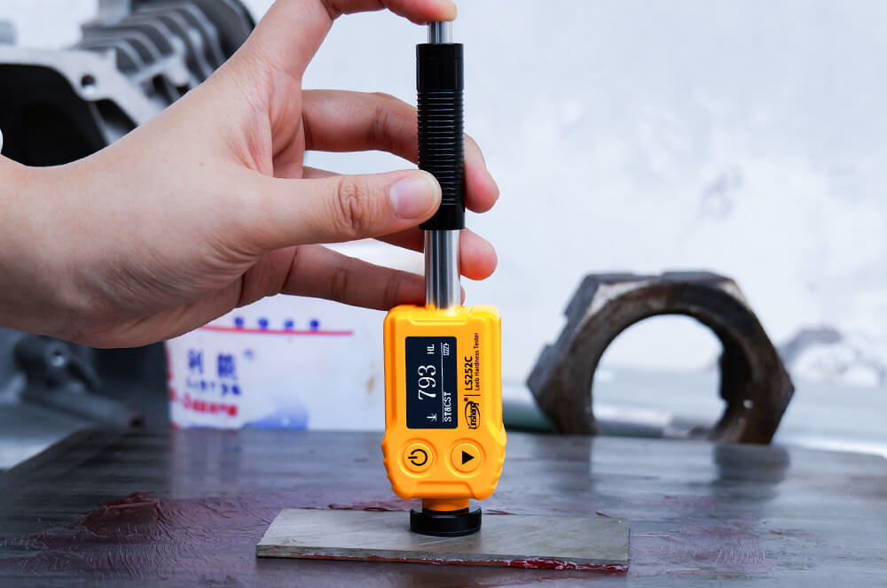
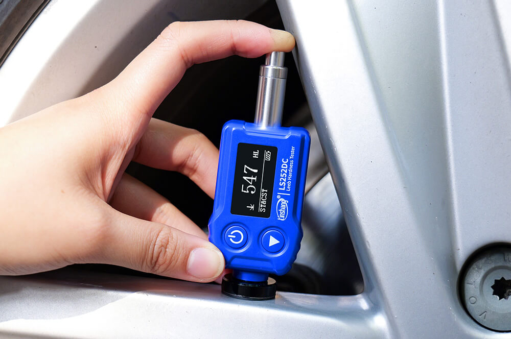
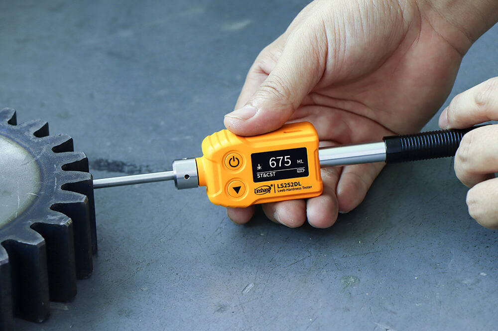
Leeb hardness values use the symbol “HL”, followed by one or more letters indicating the impact device type:
HL+D — for general metal parts.
HL+C — for small, thin parts and surface-hardened layers.
HL+DC — for inner walls of pipes or narrow areas.
HL+DL — for narrow slots or gear tooth surfaces.
HL+G — for large, heavy castings and forgings with rough surfaces.
HL+(D+15) — for small or narrow contact areas, such as grooves or recessed surfaces.
HL+E — for very hard materials.
Recommended Device:
5. Suitable Testing Materials
Leeb hardness testers are suitable for testing the hardness of various metals. They are often used for mold cavities, machine tool guide rails, automotive mold steel rails, bearings, pressure vessels, turbine generators, and large or heavy forged parts during on-site inspections. They can also easily measure parts with limited space, such as grooves and inner holes.
6. Advantages and Disadvantages
Advantages:
Can test workpieces that bench-top testers cannot.
Small and lightweight, ideal for on-site testing.
Easy to use with high testing efficiency.
Causes minimal damage to the sample surface.
One main unit can connect to different types of impact devices.
Leeb hardness values can be converted to Brinell, Rockwell, or Vickers values.
Disadvantages:
Requires certain sample mass and thickness; coupling is needed if not met.
Lower accuracy compared to Brinell and Rockwell methods.
Sample surface must be clean and smooth; coatings, oil, or scale can affect results.
V. Webster Hardness Tester
1. Principle
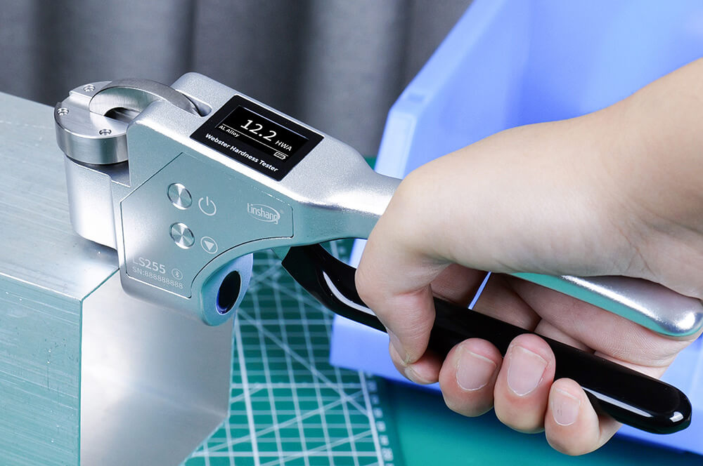
The Webster hardness tester works by pressing a steel indenter with a specific shape into the surface of the material under a set test force. The hardness is indicated by the depth of penetration: a shallower indentation means higher hardness, while a deeper one means lower hardness. In practice, the tester indirectly measures hardness by checking how deep the indenter goes into the material.
2. Calculation Method
A penetration depth of 0.0125 mm equals one Webster hardness unit (HW).

3. Classification of Webster Hardness Testers
Hardness testers are categorized into three types — A, B, and C — depending on the specific combination of indenter geometry and the nominal elastic coefficient of the loading spring. Each type is designed for testing specific materials to ensure accurate and reliable measurements.
Type A hardness testers, designated as HWA, are suitable for testing aluminum alloys.
Type B hardness testers, designated as HWB, are used for copper alloys and mild steel.
Type C hardness testers, designated as HWC, are intended for pure copper.
The value preceding the symbol (HWA/HWB/HWC) represents the measured hardness value.


Recommended Device:
Digital display, easy to read
Multiple hardness scales for quick switching, no manual chart needed
No-disassembly reference calibration and hardness calibration technology
High accuracy, verified by authoritative metrology inspection
4. Suitable Testing Materials
The Webster hardness tester is suitable for rapid, non-destructive testing of metals such as aluminum alloys, soft steel, copper alloys, and pure copper. It works well on profiles, pipes, and sheets, making it convenient for use on production lines, sales sites, or construction sites.
5. Advantages and Disadvantages
Advantages:
Portable and compact, suitable for on-site use.
Fast measurement; hardness is displayed immediately.
Values can be converted to Rockwell, Vickers, or Brinell scales.
Small indentation, causing minimal impact on appearance or performance.
Ideal for large-scale, piece-by-piece testing of profiles or thin sheets.
Disadvantages:
Limited to low-hardness materials; not suitable for hard metals like steel.
Sample surface must be smooth; dirt or debris can affect accuracy.
VI. Ultrasonic Hardness Tester
1. Principle
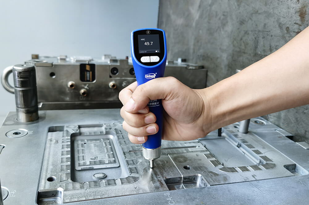
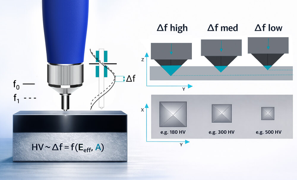
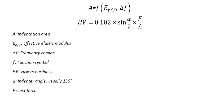
The ultrasonic hardness tester measures metal hardness using the ultrasonic contact impedance method. A vibrating rod with a diamond pyramid indenter oscillates at its natural frequency. When the indenter presses the material surface with a constant load, the contact causes a slight change in the resonance frequency. This change is converted into an electrical signal by a piezoelectric ceramic. The instrument then calculates the hardness using the material’s elastic modulus and can convert it into various common hardness units. In simple terms, the tester measures changes in ultrasonic vibrations from the diamond indenter on the material surface to calculate hardness.
2. Calculation Method
Recommended Device:
Small indentation, non-destructive measurement
Easy operation for measuring flat, small, thin or irregular parts
9 hardness scales: HRC, HRB, HRA, HRE, HRF, HV, HB, HL, HS
High precision, good repeatability
3. Suitable Testing Materials
Ultrasonic hardness testers can measure surface hardness of bearings, thin-walled parts, molds, fixtures, gear flanks, pipe inner walls, small forgings, castings, and welds. They are ideal for large, hard-to-move workpieces, complex-shaped components, and curved or irregular surfaces.
4. Advantages and Disadvantages
Advantages:
Non-destructive testing; small indentation preserves surface integrity.
High testing efficiency; suitable for on-site measurements.
Flexible use; the probe can measure at various angles.
Supports data storage and transfer, with automatic conversion between hardness scales.
Color display makes reading values easy.
Disadvantages:
For non-uniform materials or those with large differences in elastic modulus, multi-point calibration is needed.
Surface roughness and sample thickness can affect accuracy; periodic calibration with standard blocks is required.
Higher purchase and maintenance costs compared to Leeb and similar testers.
The above provides an overview of the testing principles, applications, and advantages and disadvantages of six commonly used hardness testers. We hope this information helps you better understand and choose the hardness testing solution that best suits your needs. If you have any further questions or would like more detailed information, please feel free to contact us!
Get in Touch
If you have any questions or requirements, please contact us and we will get back to you right away.
